1 / 5
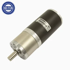
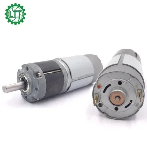
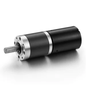
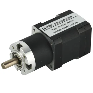
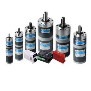
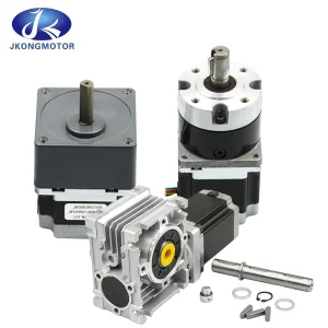
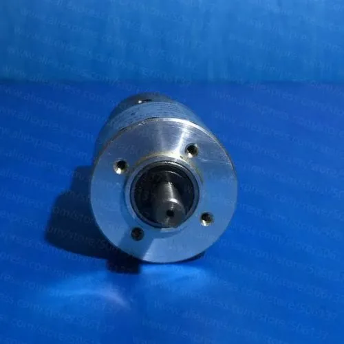
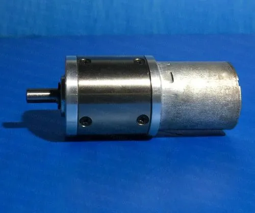
The gear reducer is a high-precision planetary gear reducer machined from robust metal materials. Following specialized quenching and heat treatment, the gears achieve an optimized structural state, ensuring exceptionally smooth operation and remarkably low running noise. Powered by a self-driven brushless DC (BLDC) motor design, installation space is greatly conserved, enabling a highly simplified mechanical configuration.
| Stage of Gearbox | STAGE 1 | STAGE 3 | STAGE 4 |
|---|---|---|---|
| Type No. | GSP-5-42B30 | GSP-24-42B30 | GSP-116-42B30 |
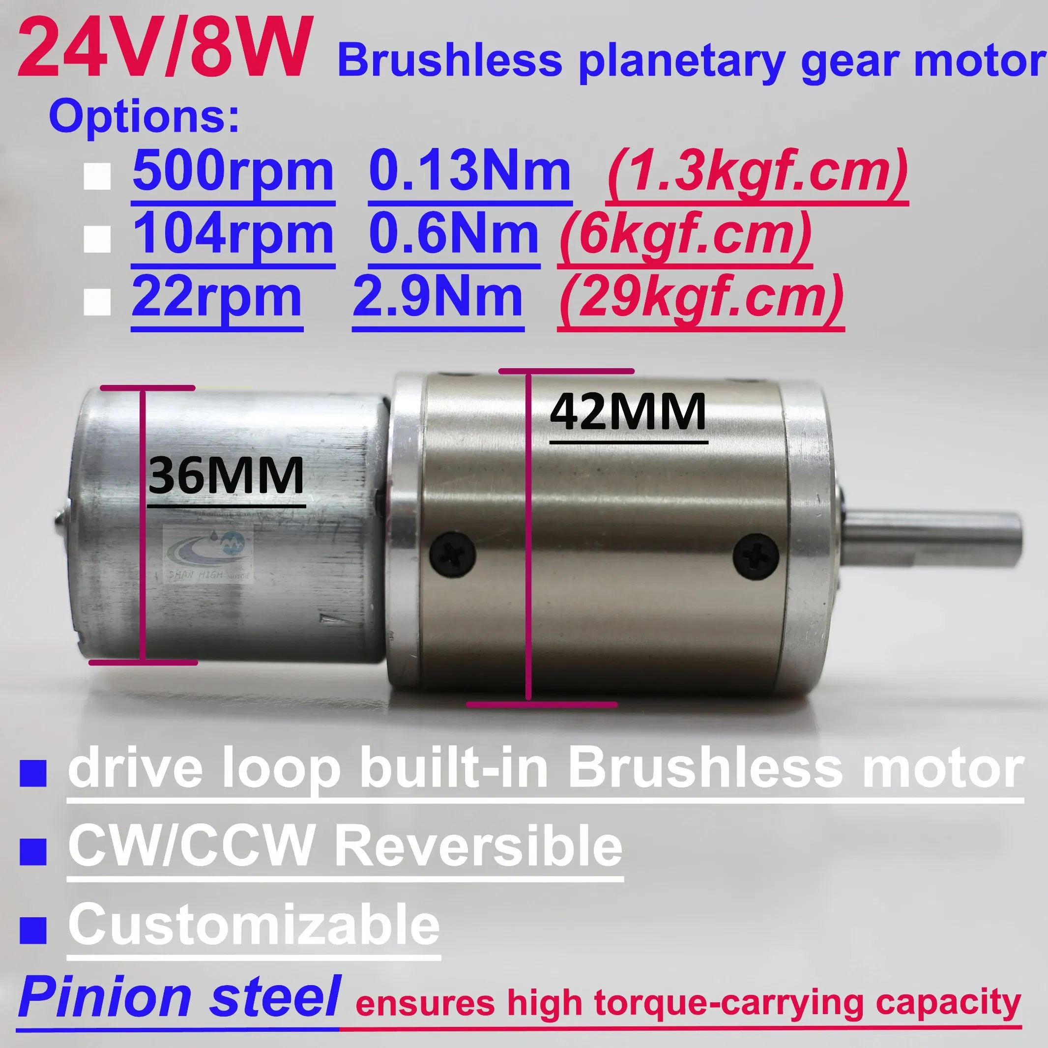
| Allowable Continuous Speed | 500rpm | 104rpm | 22rpm |
| Admissible Continuous Torque | 0.13 N.m | 0.60 N.m | 2.90 N.m |
| Weight | 328g | 396g | 465g |
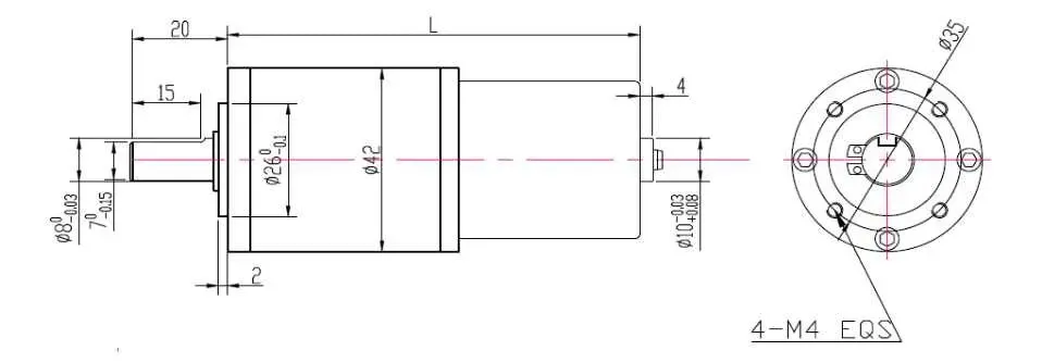
| Length "L" | 75.0mm | 86.0mm | 96.0mm |
| Supply Voltage | DC 24V | ||
| Rated Input Current | 0.5A | ||
| Rated Motor Power | 8W | ||
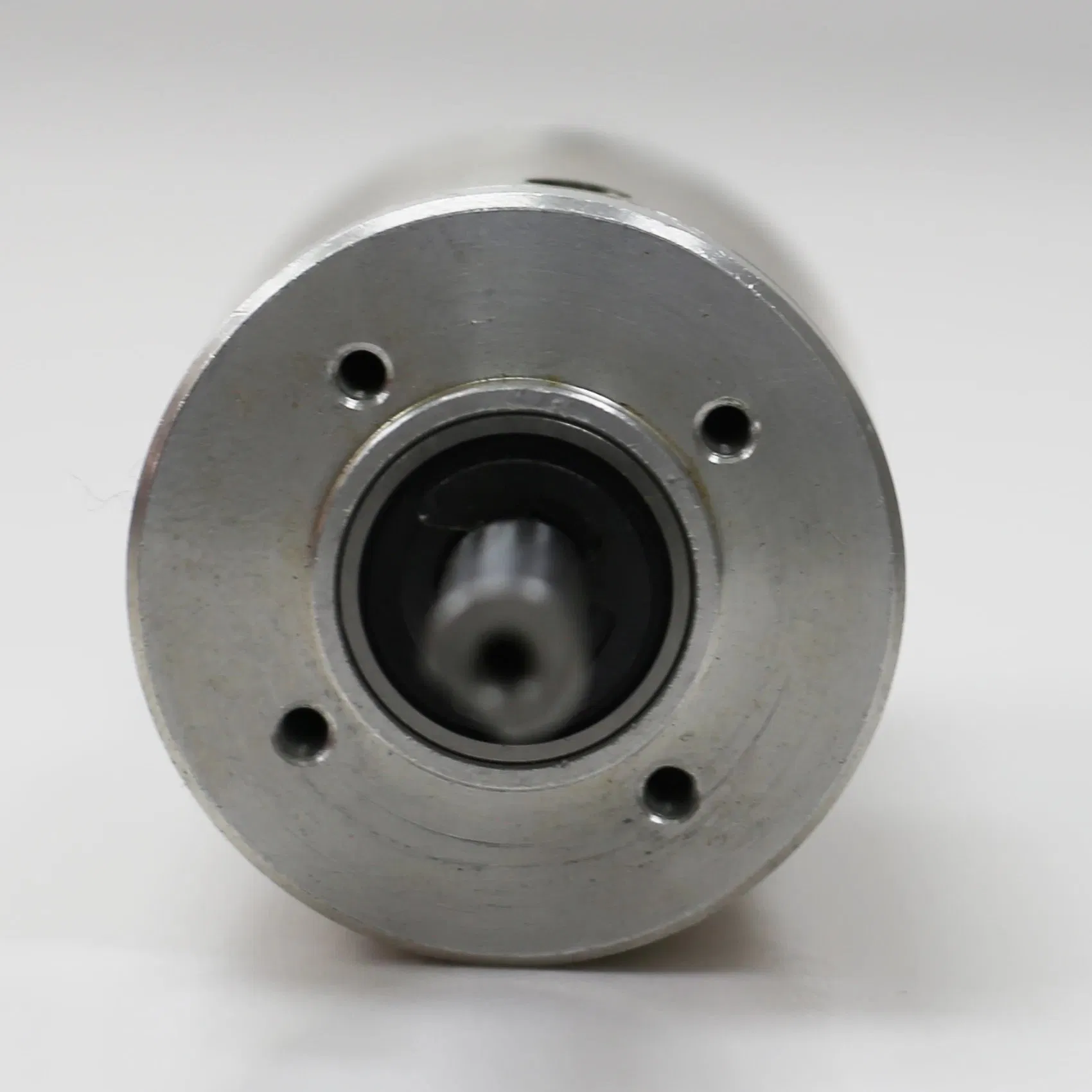
| Allowable Radial Load | ≤ 50N | ||
| Allowable Axial Load | ≤ 30N | ||
| Max. Shaft Press Fit Force | 150N | ||
| Operating Ambient Temp | 0ºC ~ 50ºC | ||
| Life Expectancy | 10,000 Hours | ||
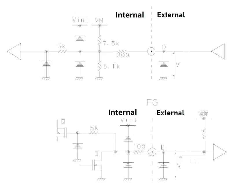
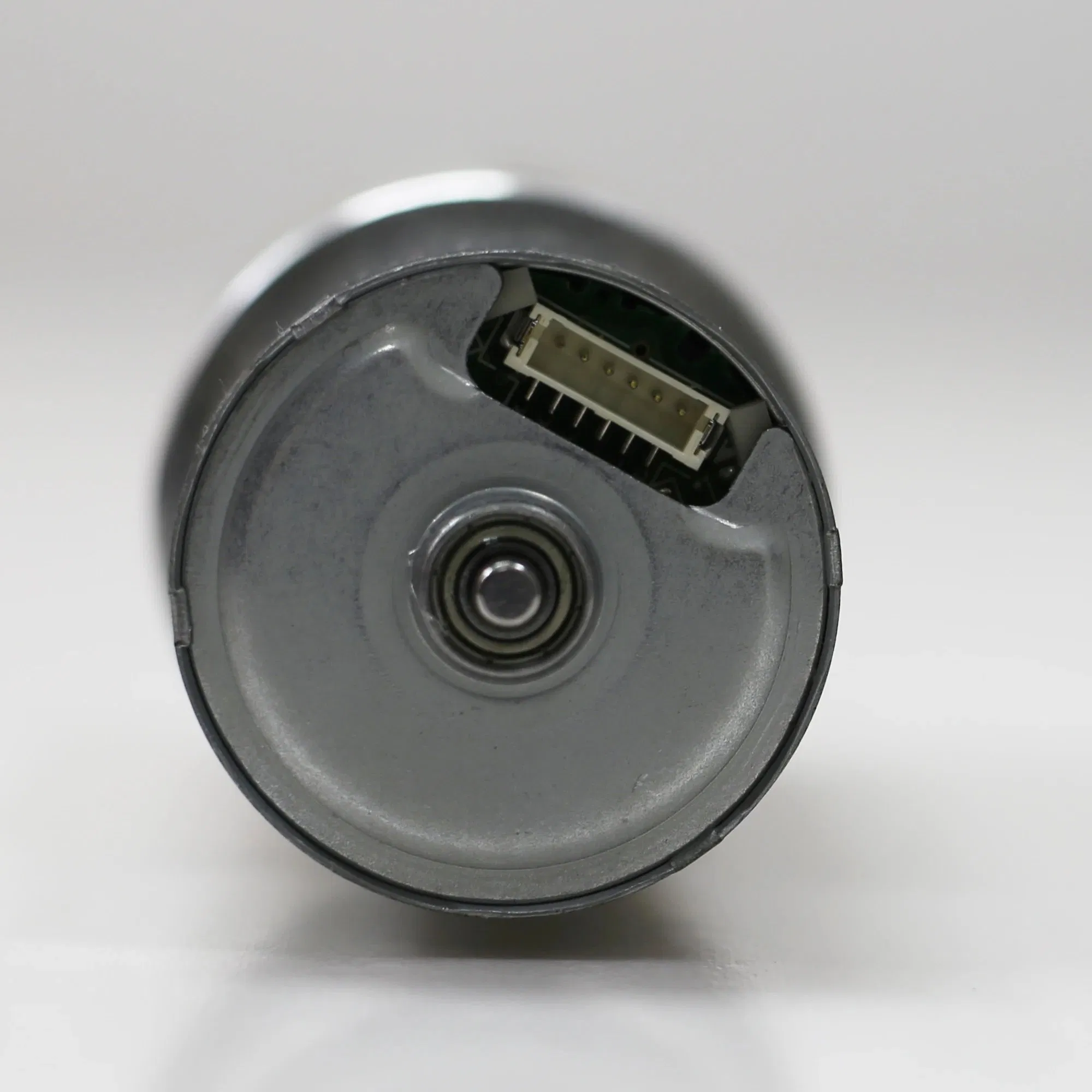
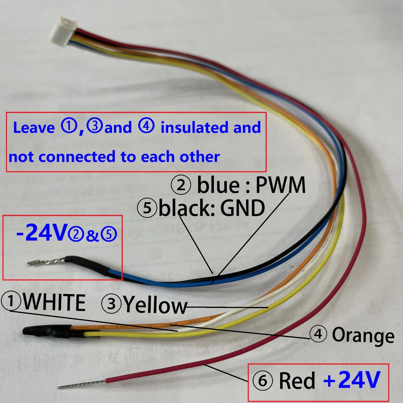
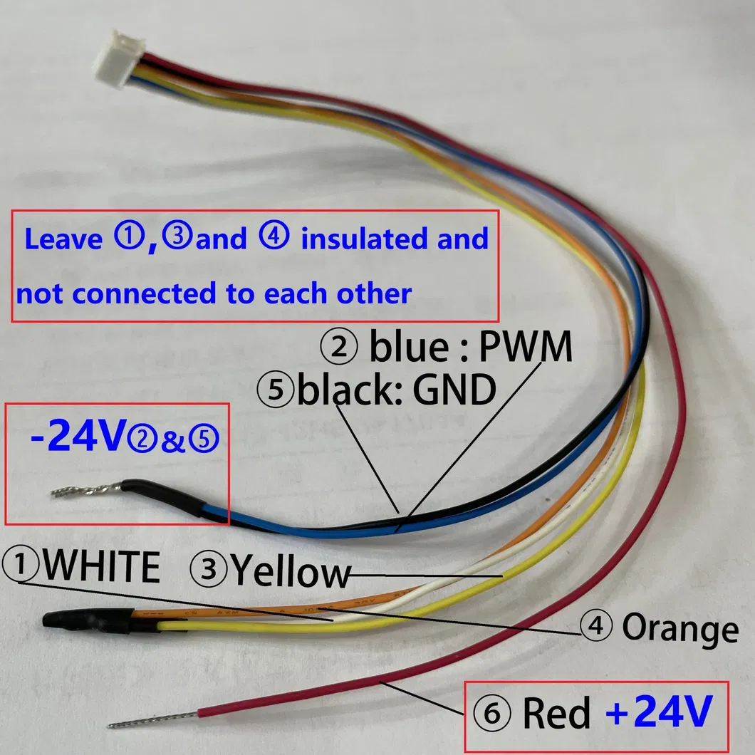
| No / Color | Signal | I/O | Specification | Note |
|---|---|---|---|---|
| 1. WHITE | BRAKE | IN | 0 - 5V VIH: 2.0V Min VIL: 0.8V Max |
High: Motor motion Low: Motor stop |
| 2. BLUE | PWM | IN | 0 - 5V VIH: 2.0V Min VIL: 0.8V Max Min Freq: 330Hz |
Recommended Input Frequency: 20KHz - 30KHz |
| 3. YELLOW | FG | OUT | 6V Max VOL: 0.5V Max Max Current: 2mA Pulse count: 6 pulses/round |
FG signal output is open drain, requires external pull-up resistor. |
| 4. ORANGE | CW/CCW | IN | 0 - 5V VIH: 2.0V Min VIL: 0.8V Max |
High: Clockwise (CW) Low: Counter-Clockwise (CCW) |
| 5. BLACK | GND | IN | Ground | System Ground Reference |
| 6. RED | VM | IN | DC 24V | Power Supply Input |
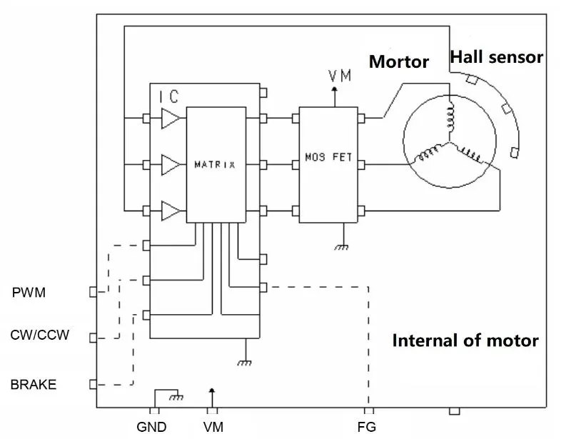
Connect the wiring as follows for immediate operation upon power-up:
| Item | Specification |
|---|---|
| Rated Voltage | DC 24 ± 10% [V] |
| Min Operating Voltage | DC 16 [V] |
| Max Operating Voltage | DC 26.4 [V] |
| Motor Type | 3 phases 12 poles BLDC with 3 Hall Sensors |
| Rotation Direction | CW / CCW |
| Bearing Type | High Grade Ball Bearing |
| Item | Specification | Note |
|---|---|---|
| Dielectric Strength | AC 600V, 1 sec, 1mA Max | Test between shorted terminals & case |
| Insulation Resistance | DC 500V, 10MΩ Min | Test between shorted terminals & case |
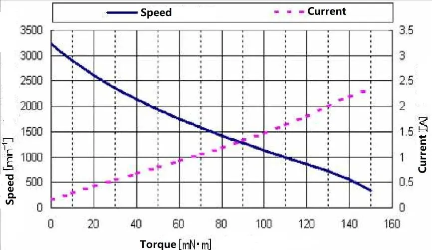
| No Load Current | 0.24A Max | At DC 24V |
| No Load Speed | 3300 ± 15% [min-1] | At DC 24V |
| Item | Specification | Note / Protective Action |
|---|---|---|
| Current Limit | 3[A] Typ | Limits maximum operating current flow. |
| Stop Temperature Protection | 165[ºC] ± 15[ºC] (IC Ambient) |
|
| Motor Self-Lock Protection | 2[sec] Typ | Motor safely powers off automatically if locked for specified duration. Power cycle resets to normal work mode. |